Power Amplifier for B–H Characterisation
A transformer-less, direct-coupled linear amplifier that drives magnetic cores from 50 Hz to 250 kHz, so their B–H loops can be measured across four decades of frequency.
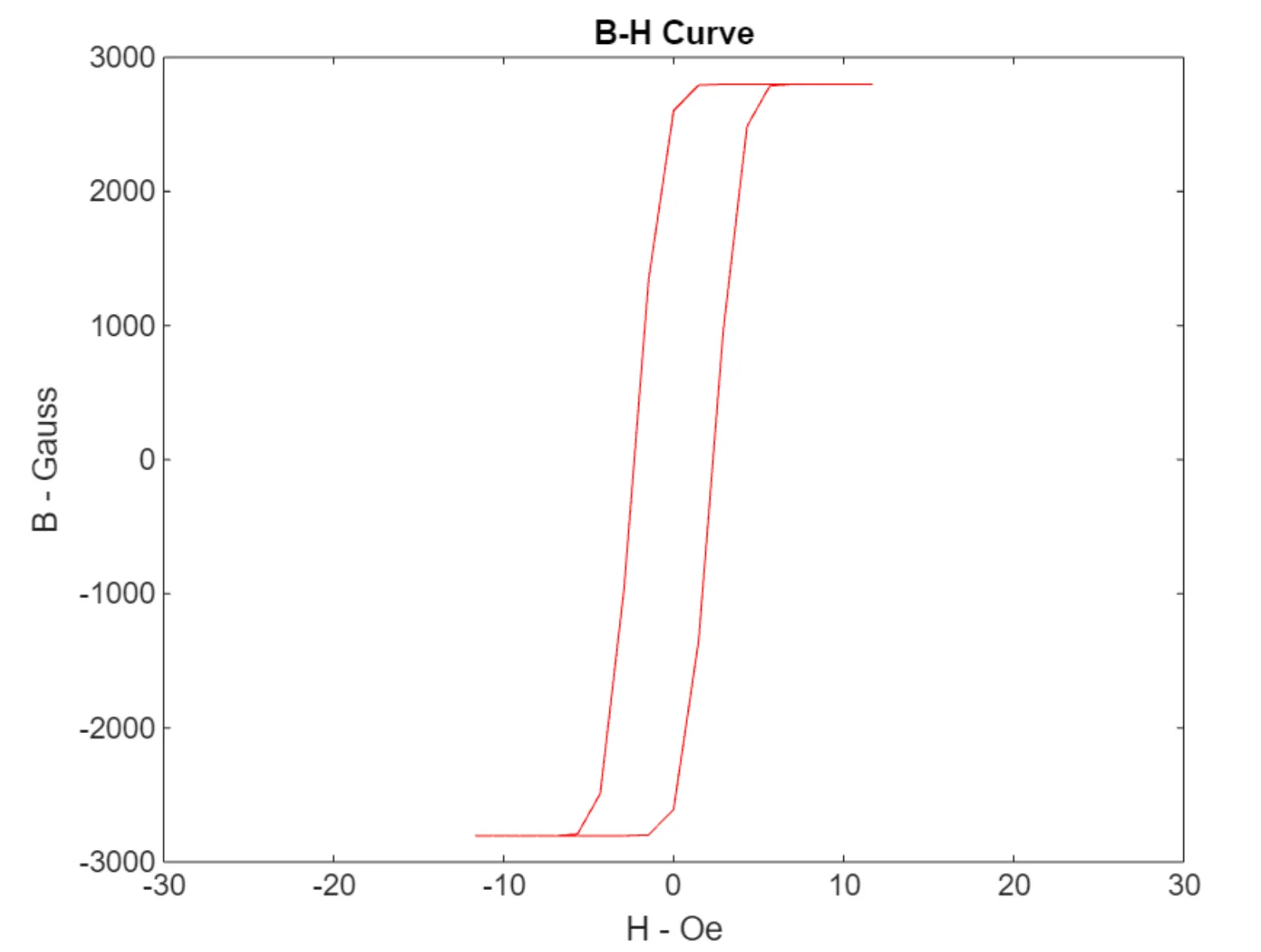
To characterise a magnetic material you drive a toroidal core through its hysteresis loop and measure what comes back — B against H. Doing that honestly means driving it at the frequencies it will actually be used at, which for modern power electronics means well past audio.
That is the difficulty. A transformer-coupled amplifier is easy to build and useless here: the transformer imposes its own low-frequency limit and its own phase behaviour, and you end up measuring the transformer.
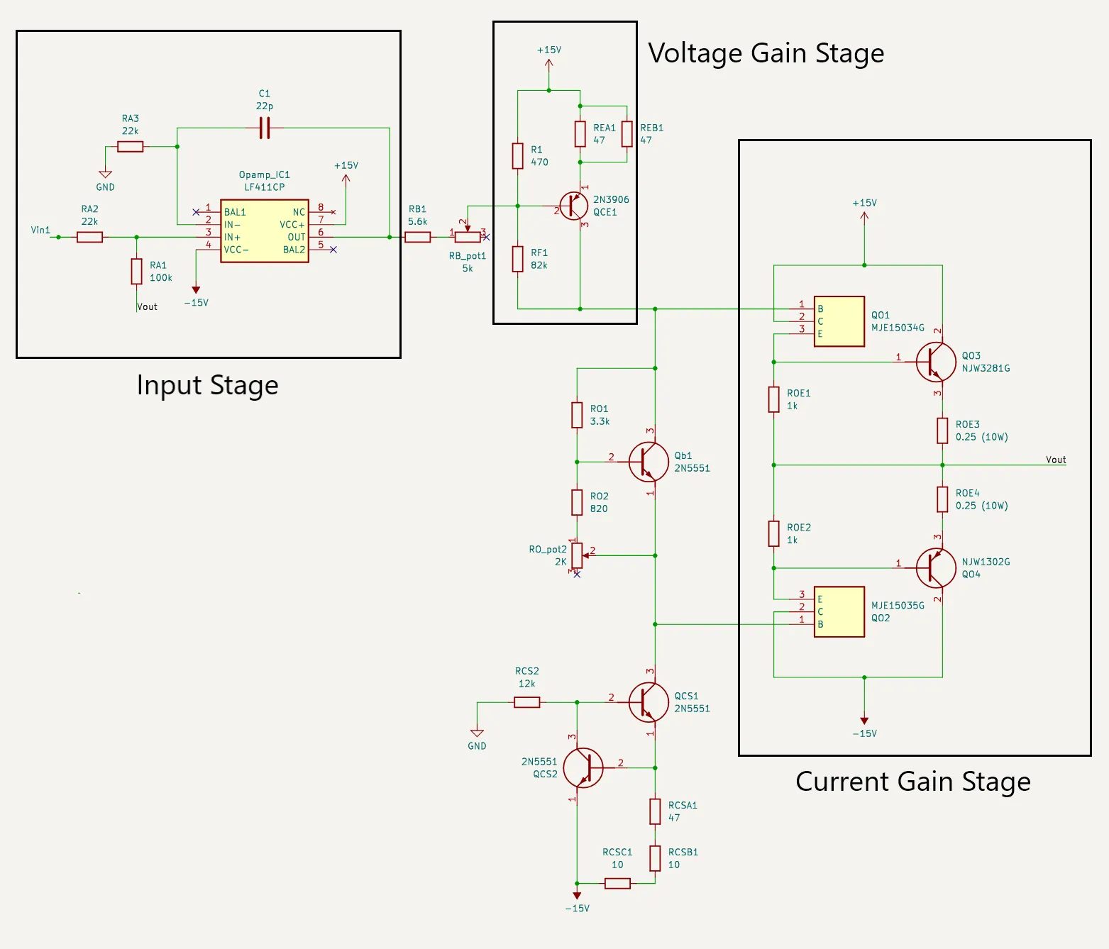
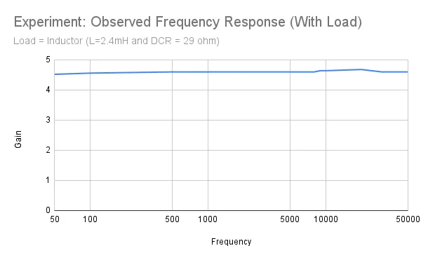
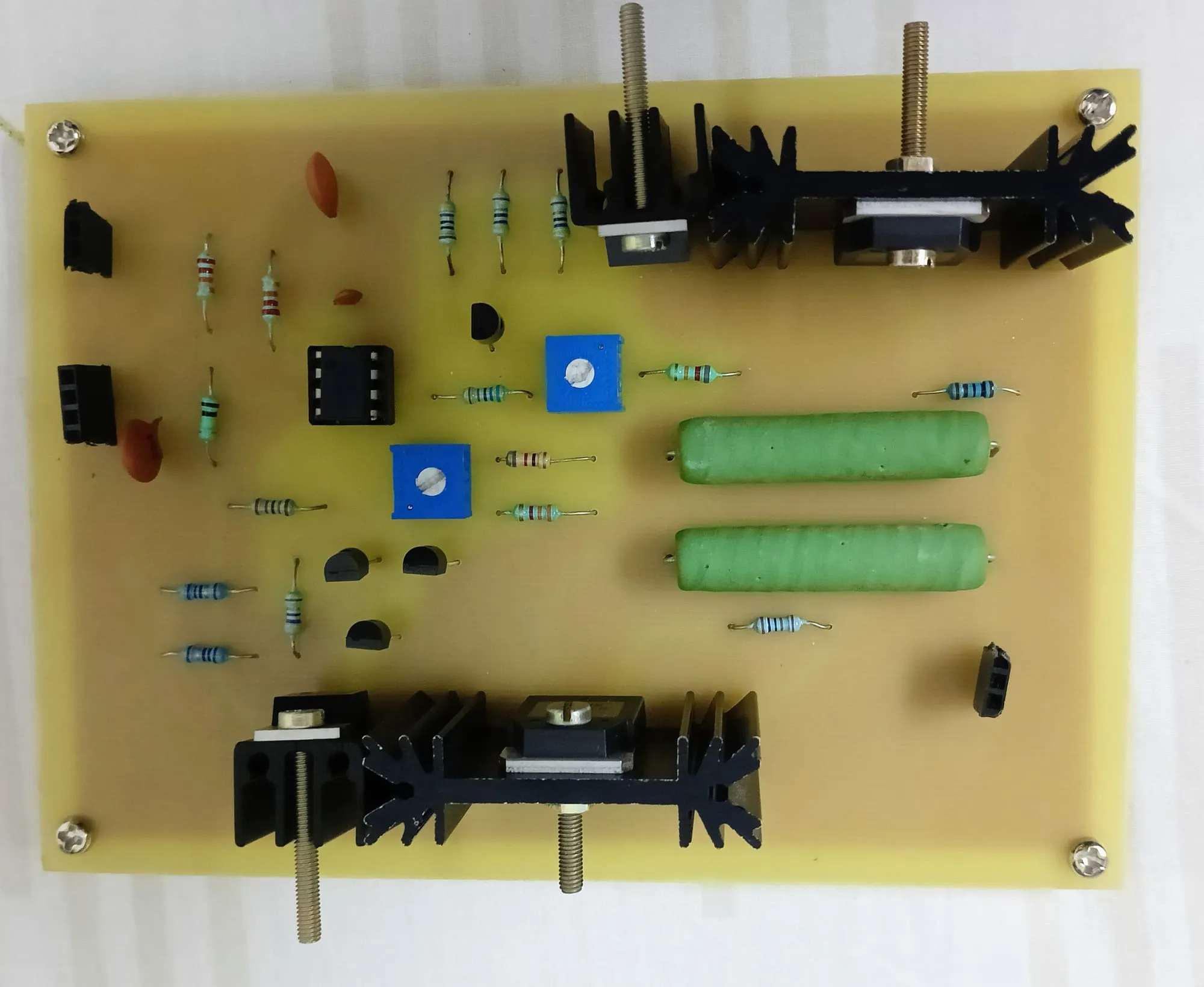
So this one has no transformer. It is a multi-stage, direct-coupled linear amplifier — an input stage, a voltage gain stage and a current gain stage — flat from 50 Hz to 250 kHz, with a gain of about 4.6, running from a ±60 V supply and holding 2.5 – 3 A continuously.
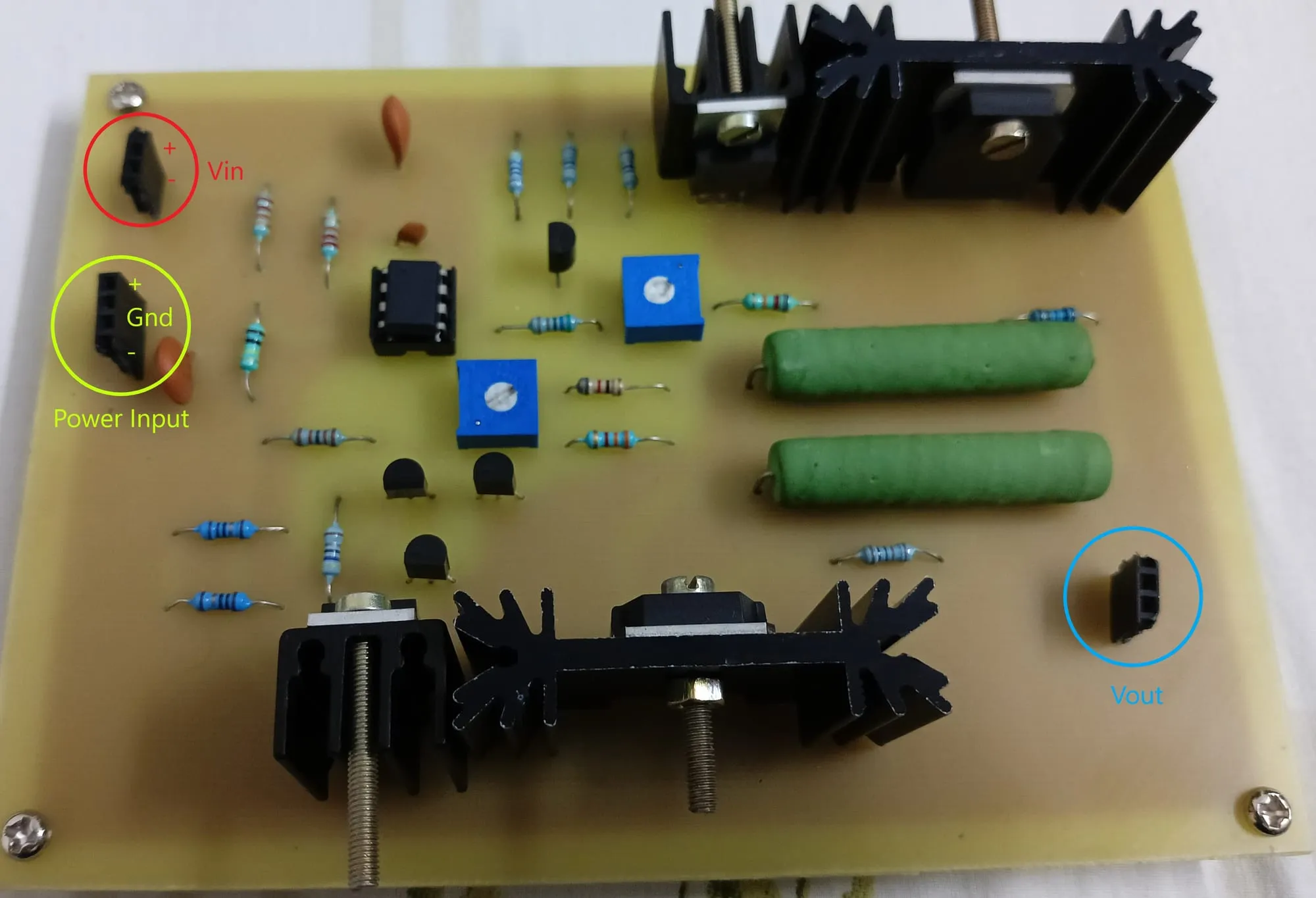
Linear, not switching, and that is a deliberate cost. A class-D output stage would be far more efficient and would put its switching noise directly into the measurement. Here the heat is the price of a clean loop, which is why so much of the board is heatsink.
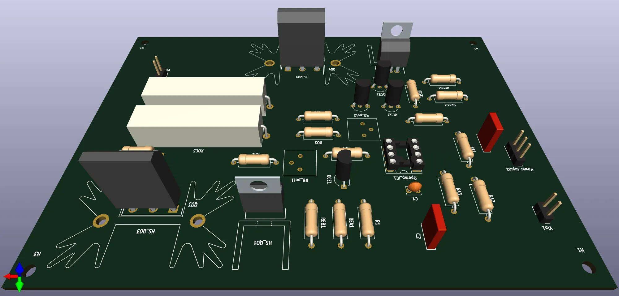
The repository carries the KiCad and Proteus files, the toroid design calculations, the measured frequency response against the simulated one, and a user manual — enough to rebuild it.
Gallery
0505